
Sheet 05 of 15
Flanges on Several Edges: Corners, Gap and Corner Reliefs
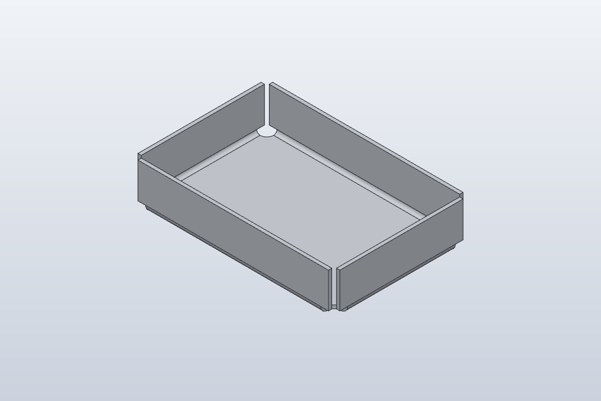
In 6 minutes you'll fold up all four walls of a tray in one Flange, see how SolidCraft closes the corners with a gap, and choose a corner relief shape.
- Part
- Corners and Reliefs
- Rule
- Steel 2mm
- Sheet
- t 2 · R 2 · K 0.4
- Time
- 6 min
- Status
- Open
OP 10Watch
Video in productionBuild along with the steps in OP 30 meanwhile.
OP 20Turn the part
Drag to turn, scroll or pinch to zoom. Flat shows the blank before it is bent: the same sheet, the same frame.
The model shows part A, for illustration. Your part has its own sizes: build it from the drawing in OP 30.
OP 30Build it in SolidCraft
Part A of 8. Every learner gets a part with its own sizes, so the values you check below are yours to find.
A new part has new sizes. It clears this sheet's checks and ticked steps; your quiz answers stay.
The picture shows part A, for illustration. Build your part from the drawing and the sizes listed here.
- Rule
- Steel 2mm
- Thickness
- 2 mm
- Bend radius
- 2 mm
- K-factor
- 0.4
As typed in this exercise
- Sketch Base on XY: rectangle (0, 0) to (120, 80)
- Flange: height 25
Your task
Build this tray from the drawing above.
- The rule from the drawing's notes (leave its corner values as they come), then the base as in lessons 1 to 3.
- Flange on all four top edges in one go, the long front edge first: the height from the drawing, angle 90°, Bend Position Inside.
- Flat Pattern: read both numbers of the Flat size.
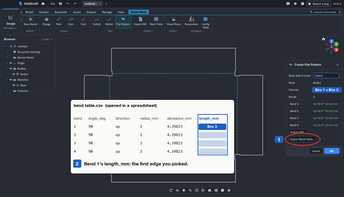
- New this time, the bend table: in the Flat Pattern press Export Bend Table…, save the CSV, open it and read length_mm of bend 1.
- Edit the flange: under Advanced, Corner Relief Shape Round, Corner Relief empty. Read bend 1's length again.
- Give the tray the Physical Material Aluminum and read its Mass in Properties; then Steel, and read it again.
What to write down
- Boxes 1 and 2: Both numbers of the flat size (they don't change with the relief shape).
- Box 3: Bend 1's length with the Notch corner (the rule's default).
- Box 4: Bend 1's length with the Round corner relief.
- Boxes 5 and 6: The tray's mass in aluminum and in steel, in grams (the Round relief tray; type the number only).
Bend 1 is the first edge you picked. Type the values below and press Check. The bend table opens in any spreadsheet app or text editor.
OP 40Inspect
Enter what SolidCraft shows you. Each value is checked against SolidCraft's own result, within the tolerance shown. Nothing you type leaves this page.
Stuck? Compare with the finished part
This opens once you've checked every box at least once: try it yourself first.
Open it in SolidCraft (File › Open) next to yours and compare the timeline, the rule and each feature's sizes: the first one that differs is where yours went wrong.
exercise · Steel 2mm · t 2 · R 2 · K 0.4 · all dimensions in mm, from the blank's left and bottom edgesFlat blank 162.797 × 122.796 mm · 4 bends
| Bend | Angle | Dir. | R mm | Length mm | Allowance mm |
|---|---|---|---|---|---|
| 1 | 90° | up | 2 | 112 | 4.398 |
| 2 | 90° | up | 2 | 72 | 4.398 |
| 3 | 90° | up | 2 | 112 | 4.398 |
| 4 | 90° | up | 2 | 72 | 4.398 |
exercise-round · Steel 2mm · t 2 · R 2 · K 0.4 · all dimensions in mm, from the blank's left and bottom edgesFlat blank 162.797 × 122.796 mm · 4 bends
| Bend | Angle | Dir. | R mm | Length mm | Allowance mm |
|---|---|---|---|---|---|
| 1 | 90° | up | 2 | 104 | 4.398 |
| 2 | 90° | up | 2 | 64 | 4.398 |
| 3 | 90° | up | 2 | 104 | 4.398 |
| 4 | 90° | up | 2 | 64 | 4.398 |
exercise-steel · Steel 2mm · t 2 · R 2 · K 0.4 · all dimensions in mm, from the blank's left and bottom edgesFlat blank 162.797 × 122.796 mm · 4 bends
| Bend | Angle | Dir. | R mm | Length mm | Allowance mm |
|---|---|---|---|---|---|
| 1 | 90° | up | 2 | 104 | 4.398 |
| 2 | 90° | up | 2 | 64 | 4.398 |
| 3 | 90° | up | 2 | 104 | 4.398 |
| 4 | 90° | up | 2 | 64 | 4.398 |
OP 50Quiz
Q1Why pick all four edges in the same Flange?
The corners are closed, with the rule's gap, only between flanges of one feature.
Q2Where does the gap between two walls at a corner come from?
Flange Gap is a rule value; by default it equals the thickness.
Q3You switch the corner relief from Notch to Round. What changes?
The round relief is cut out of the corner and the bends stop where it begins; the flat size stays the same.
Every value is within tolerance. This sheet is done.
Sheet 06: Contour Flange